September 03, 2014

Independent Study - Rendering

I am experimenting with Independent Study with my professor of probably one of my favorite classes I've ever taken (Rendering).  Unfortunately my school isn't offering the next class in the sequence but I'll be pursuing my studies all the same.

I really like Inigo Quilez's work, as I've said before, and if I could reach half of his shader writing proficiency I would be happy.  I'm interested in how mathematical shapes are visualized, namely fractals.  I had implemented the geometry for a torus knot last semester and I'd like to now move away from 3D meshes and create everything in the fragment shader, like they do on shadertoy.  To visualize this I'll need to learn how to implement a ray tracer, so that's my first project.

When starting off projects I like to start with very small, very dumb steps so I feel smarter each time I finish a small milestone.  By next week I would like to implement a ray tracer that accurately visualizes a sphere.

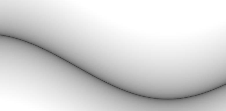
I've started by drawing a rectangle and creating a "camera".  I calculate the distance from the camera to each pixel for each y component, and use that to color the rectangle.  The camera can move up and down its axis so we can see the differences in shading.

Here is the code:
vec3 camera = vec3(0.0, iMouse.y / iResolution.y, 0.0);

bool is_in_x_range(float x, float left, float right)
{
    return (x > left && x < right);
}

bool is_in_y_range(float y, float bottom, float top)
{
    return (y > bottom && y < top);
}

bool is_in_box(vec2 uv) {
    return (is_in_x_range(uv.x, 0.3, 0.7) &&
        is_in_y_range(uv.y, 0.3, 0.7));
}

void main( void )
{
    vec2 uv = gl_FragCoord.xy / iResolution.xy;
 
    float x_col = 1.0, y_col = 1.0, z_col = 1.0;
 
    if (is_in_box(uv)) {
        y_col = distance(camera.y, uv.y);
    }

    gl_FragColor = vec4(x_col, y_col, z_col, 1.0);
}

And here it is in action:
(gif would be better here, I'll download some new software)

Very simple but it's a start..  Next thing to do would be to add a light, make it 3D (this is where a sphere would be easier), etc. etc.

April 24, 2014

Class project - torus knot

My goodness, it's been a while since I've posted in here.

My intrigue for shader programming hasn't left me, but the semester is nearing to a close and things are very busy now.  But we had a final project in my Rendering class where we were required to implement either bump mapping or environment mapping and I chose the latter.

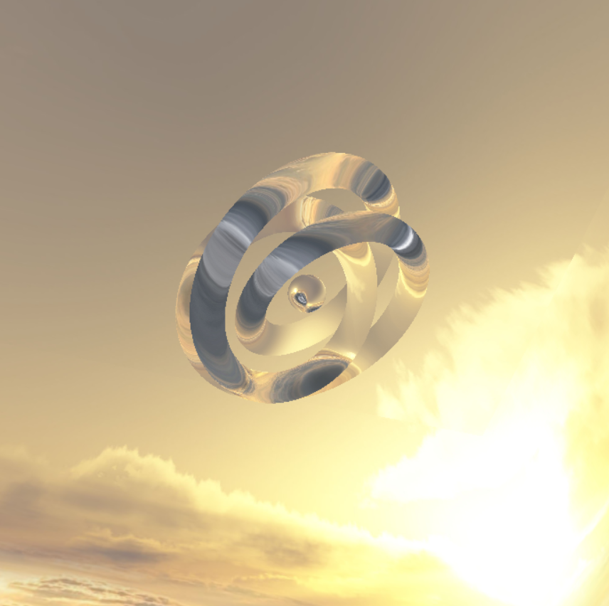
I've been really interested in mathematical shapes.  I wanted to implement a 3D Julia set but I can only use VBOs to implement the geometry and the professor thought it would be too difficult, so I implemented a torus knot instead.  It wasn't easy either but at least it was doable.

I'll attach a video later but here's a screenshot:


Basically the camera rotates around the knot and the knot rotates along two of its axes.  It looks pretty cool, I wish I was able to implement clouds in the fragment shader and it would be really cool.

April 02, 2014

Drawing circle with GLSL

I'm still dabbling with really simple GLSL code but I finally understand how to draw a circle so I'll just write it down before I forget.

Here's the code:

void main(void)
{
vec2 p = (2.0 * gl_FragCoord.xy - iResolution.xy) / min(iResolution.x, iResolution.y);
float h = length(p.xy);
float alpha = smoothstep(0.99, 1.0, h);

gl_FragColor = vec4(mix(vec3(0.0), vec3(h), alpha), 1.0);
}

So p basically just scales down the coordinates of our current fragment so it's kind of like normalized device coordinates but accounts for the window dimensions.

I think h just measures the length of the current fragment from the center of the screen (note that the center of the screen is 0,0).  Can also think of it as the radius.

And alpha is set to 0.0 if the length (we can also think of it as radius) is less than 0.99, set to 1.0 if the radius is greater than 1.0.  Between it's interpolated between a very small value (meaning the edge of the circle will be sharp, not blurry).

And finally we set the fragment color.  Remember that the mix function takes two vectors (basically two candidates for the fragment's color) and an alpha value, that we can think of the weight of the second vector.  For this code it's all or nothing for each vector - as explained above, if the current fragment is within the radius of the circle then h will have been set to 0, so vec3(0.0), which is black, will be drawn.  If the current fragment is outside of the radius then h will have been set to 1, so vec(h) (which is [1.0, 1.0, 1.0]) is what will be drawn, which is the part outside the circle.

Not posting a picture of a circle because we all already know what it looks like.

March 28, 2014

Understanding smoothstep

Since I see it used around a lot.

To start off with, here is an image:


Corresponding to this code:
void main(void)
{
vec2 uv = gl_FragCoord.xy / iResolution.xy;
gl_FragColor = vec4(vec3(uv.x),1.0);
}

Pretty self explanatory.  The x value changes consistently throughout the image, from 0.0 to 1.0
And now let's compare that image with the effects of using smoothstep.
Here is using smoothstep in the range of [0.0, 1.0]:

With the code:
void main(void)
{
vec2 uv = gl_FragCoord.xy / iResolution.xy;
float f = (smoothstep( 0.0, 1.0, uv.x) );
gl_FragColor = vec4(vec3(f),1.0);
}

The image is slightly different but it's still pretty even.

But now, let's look at smoothstep in ranges of [0.0, 0.7], [0.0, 0.4], [0.0, 0.1]:


And smoothstep in ranges of [0.3, 1.0], [0.5, 1.0], [0.9, 1.0]

So it's not that smoothstep keeps uv.x within the range of, say, [0.9, 1.0] or the image would be, at its darkest, light grey.  Seems like if uv.x <= 0.9 it'll be set to 0.0 while if uv.x >= 1.0 it'll be set to 1.0.

So this is how you can get a straight line, by interpolating over a very small range of values.
For example, this is smoothstep in range of [0.509, 0.51]:


Here's code that kind of explains it:
void main(void)
{
vec2 uv = gl_FragCoord.xy / iResolution.xy;
float if_below_me_set_to_0 = 0.509;
float if_above_me_set_to_1 = 0.51;
float f = (smoothstep( if_below_me_set_to_0, if_above_me_set_to_1, uv.x) );
gl_FragColor = vec4(vec3(f),1.0);
}

Better variable names would be if_below_me_set_to_0_else_interpolate and if_above_me_set_to_1_else_interpolate but who has time for that

March 25, 2014

Demystifying GLSL

It's useful to know what the values of variables really are.

So, in Shadertoy:

iResolution.x = ~900
iResolution.y = ~500

glFragCoord.x in range of [0, 900]
glFragCoord.y in range of [0, 500]
Represents the current fragment.

Typically a vector uv is used to scale the fragment down.
uv = gl_FragCoord.xy / iResolution.xy
uv.x, uv.y in range of [0, 1]

Then, to put the coordinates in OpenGL normalized device coordinates, I've started using ndc to represent that.
ndc = (uv * 2.0) - 1.0
ndc.x, ndc.y in range of [-1, 1].

Here's a simple program I wrote to explore more GLSL:

void main(void)
{
vec2 uv = gl_FragCoord.xy / iResolution.xy;
vec2 ndc = (uv * 2.0 - 1.0);

float line = ndc.y;
float curve = cos(ndc.x);
float movement = cos(iGlobalTime + ndc.x);

float wave = line + curve * movement;

vec3 c = vec3(pow(wave, 0.2));

gl_FragColor = vec4(c, 1.0);
}

If you comment out curve and movement, and set wave to just line, you'll get this picture:

If you uncomment curve and set wave to line + curve, you'll get this:

And uncommenting movement and setting wave to line + curve + movement, it'll animate!

The first time I saw the pow function in someone elses code, I wasn't sure what it did.

It's how you get the line in the picture.
Because this is how (JUST line, no curve or movement) looks without the pow function:

But doing the pow function basically takes the positive half of the image and flips it over the horizontal axis.  This is the result of applying ever smaller values of pow (0.9, 0.5, 0.1):


Which gives us the line shape.

March 24, 2014

GLSL function - mix and clamp

As I peruse shader code written by experts (and novices) I noticed there a ton of functions I don't understand.  Two common ones I see a lot are mix and clamp, and I was really confused about what they did.

I wrote my own mix function, complete with really obvious variable names, so when I get confused again in the future I can look back on this and be like "Oh, that's what that was."

vec4 my_mix(vec4 x, vec4 y, float a) {
vec4 x_contribution = x * (1.0 - a);
vec4 y_contribution = y * a;

return x_contribution + y_contribution;
}

void main(void) {

vec4 white_layer = vec4(1.0, 1.0, 1.0, 1.0);
vec4 black_layer = vec4(0.0, 0.0, 0.0, 1.0);

float amount_of_second_layer = 0.5;

//gl_FragColor = mix(white_layer, black_layer, amount_of_second_layer);
gl_FragColor = my_mix(white_layer, black_layer, amount_of_second_layer);

}

Although I'm having a lot of fun working with this kind of fun and it is so incredibly exciting seeing the possibilities of this, it's also really hard being the n00b.  The absolute n00b.  I look on people's code online and they're like "Oh I'm an absolute beginner at this stuff" and even they are using functions that I've never used before.  It's just been a while since I've been this n00b at something.

But I love it anyway :)

// Edit
The declaration for clamp, vec4 is:
vec4 clamp(vec4 x, vec4 minVal, vec4 maxVal)
How does GLSL judge if x is "bigger" than minVal?  Does it judge solely on magnitude?  Does it compare, component by component?
Answer to my own question, they do it component by component

So here would be code to implement clamp:
vec4 my_clamp(vec4 x, vec4 minVal, vec4 maxVal) {
float x_comp = x.x < minVal.x ? minVal.x : x.x > maxVal.x ? maxVal.x : x.x;
float y_comp = x.y < minVal.y ? minVal.y : x.y > maxVal.y ? maxVal.y : x.y;
float z_comp = x.z < minVal.z ? minVal.z : x.z > maxVal.z ? maxVal.z : x.z;
float w_comp = x.w < minVal.w ? minVal.w : x.w > maxVal.w ? maxVal.w : x.w;

return vec4(x_comp, y_comp, z_comp, w_comp);
}

Ugly code sorry

Noob graphics question

Does graphics programming appreciate good coding practices, like good variable names or refactoring out functionality or short methods?  Or is it so geared towards high performance that all of the good coding practices I've learned doing C# or Java are actually bad?  For trying to learn from other people's code the best approach I've found is refactoring the code until all of the names mean something to me, but when looking on examples at shadertoy.com it seems really common to have magic numbers everywhere, and really large monolithic functions.